6x4 Dual Alternator Install
Table of Contents
DISCLAIMER AND WARNING
This is NOT a simple project. Whilst the positioning of the work and installation of brackets, components and alternators is a direct “bolt in”… that is so far from the truth! Do not attempt this unless you are familar with angle griding, soldering, modifying electrical circuits, re-routing cables and so much more.
At times in this process I was seriously wondering ‘What the hell have I done!’ and was pondering stopping and reverting back to stock. However, my mate Chris is a mechanic and he helped throughout the process. Without having all the right tools, some good experience with modifying stuff in the engine bay and core electronics and more - DO NOT ATTEMPT THIS!
Kit required
Before getting into the specifics, lets cover the bits and pieces that was used & required to complete this installation.
- Rapid Inflation Systems High Mount Alternator Kit. This is a High Mount Alternator kit suitable for VDJ 76 78 79 Series LandCruisers. Installation manuals were provided: High Mount Alternator Installation HOWTO and Intake pipe Installation HOWTO.
- High Output 240Amp 12v Alternator to suit Toyota LandCruiser VDJ70 & 200 Series
- WELDING CABLE COPPER D/INSUL - 95mm². Running the cable from the engine bay alternator to the canopy is +7m and need to ensure that there will be no voltage drop over those lengths.
Key points to be aware of
- The Jaylec 240a alternator does NOT fit on the top spot on the engine block in the dual alternator bracket.
- You have to swap the alternators and where they are installed; e.g. the stock 130a alternator to the top in the bracket and the 240a alternator to the bottom to replace the stock alternator. The 240a alternator will NOT fit the top spot.
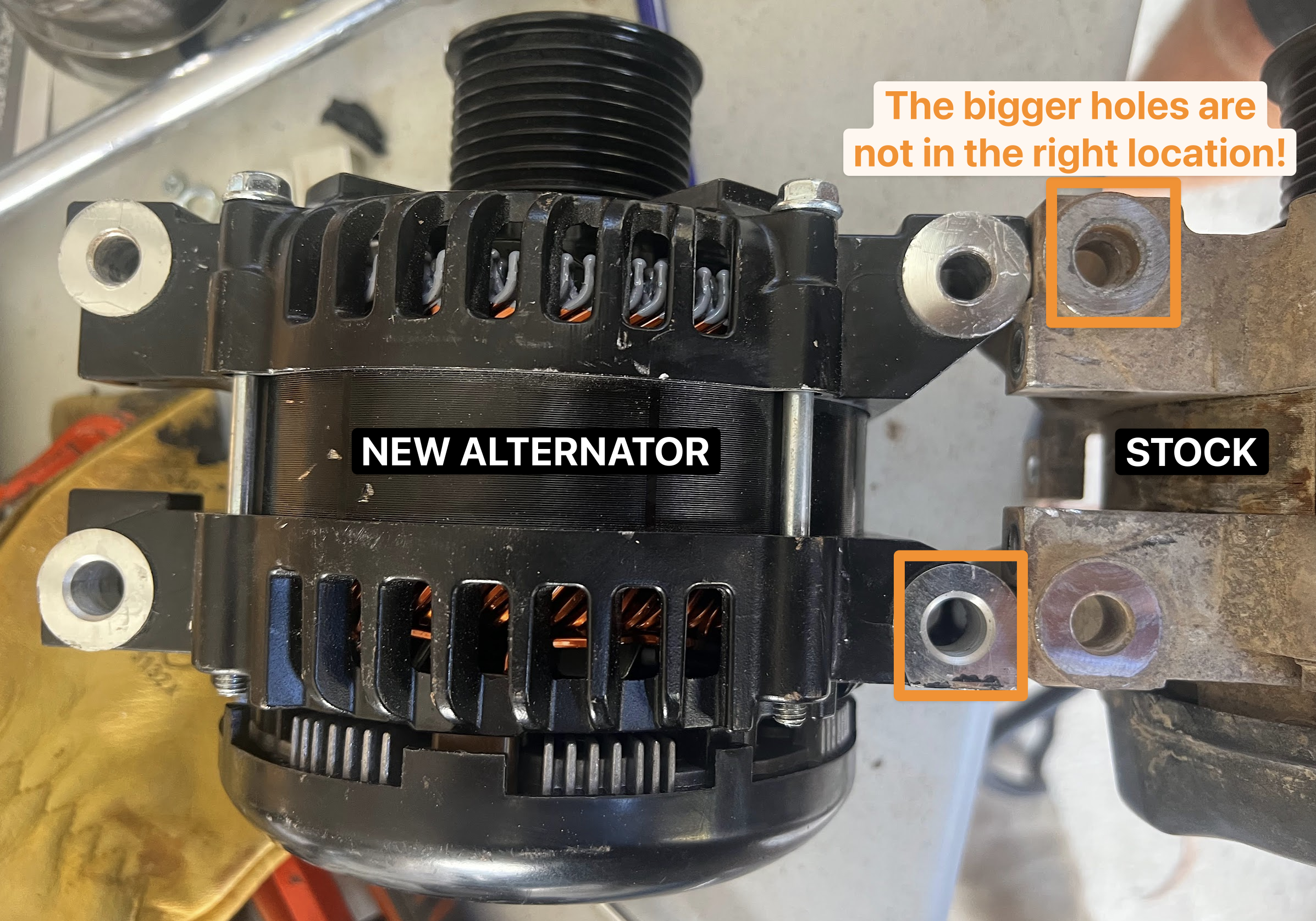
- We had to drill into the Jaylec alternator mouting holes with a 13mm driver as Jaylec must have done a manufacturing defect on this unit as it dit not sit flush on the brackets.
- You will need to reseat & move the MAF sensor.
- You will need to modify the air intake into the engine. The made up bracketry is multi piece and I will at some point get something manufactured as I do not like the many components that will end up sitting between the airbox and the air intake into the engine.
Why a dual alternator install?
First - our setup is a bit different to most others, so worth pointing that out. We have a 2014 Trakmaster Caravan which has a traditional 240v input into the van but no central inverter to power the 240v circuit. So we had to make a couple of choices - either not use 240v when camped out in the bush, use a generator, or … figure out a way to get the 48/240v setup in the car to provide somewhat reliable power to the van. Given I wanted 240v in the car to be available and it has plenty of power per se.. making the car the ‘battery’ that could provide the van power made sense.
However, the bigger problem is to ensure that we can keep the battery banks charged up… so we needed something different. The choice we landed on was to install a secondary alternator and have that dedicated to charging the 48/240v setup in the canopy. The original 48/240 setup I had, used a Safiery 3kw Scotty AI, which is rated to a 250 amp alternator… so that’s what we went with. The intent is to maximise charging rate when driving reducing the need for using a generator. It does not remove the need to use a generator at times, but that depends a bit on the type of camp and travel that you are doing.
For example, in the 2025 winter season we were camped out from June to September south of Hotham in the alpine region in Victoria Australia… and over the weekends up skiing we did not get to drive that much so did not get to charge the battery banks with the normal alternator charging (1000-1600 watts max - at best…) and would need to occasionally then use a generator to charge. Especially when camped out for several days.
Anyways, that is a bit of the background… so lets cover the installation
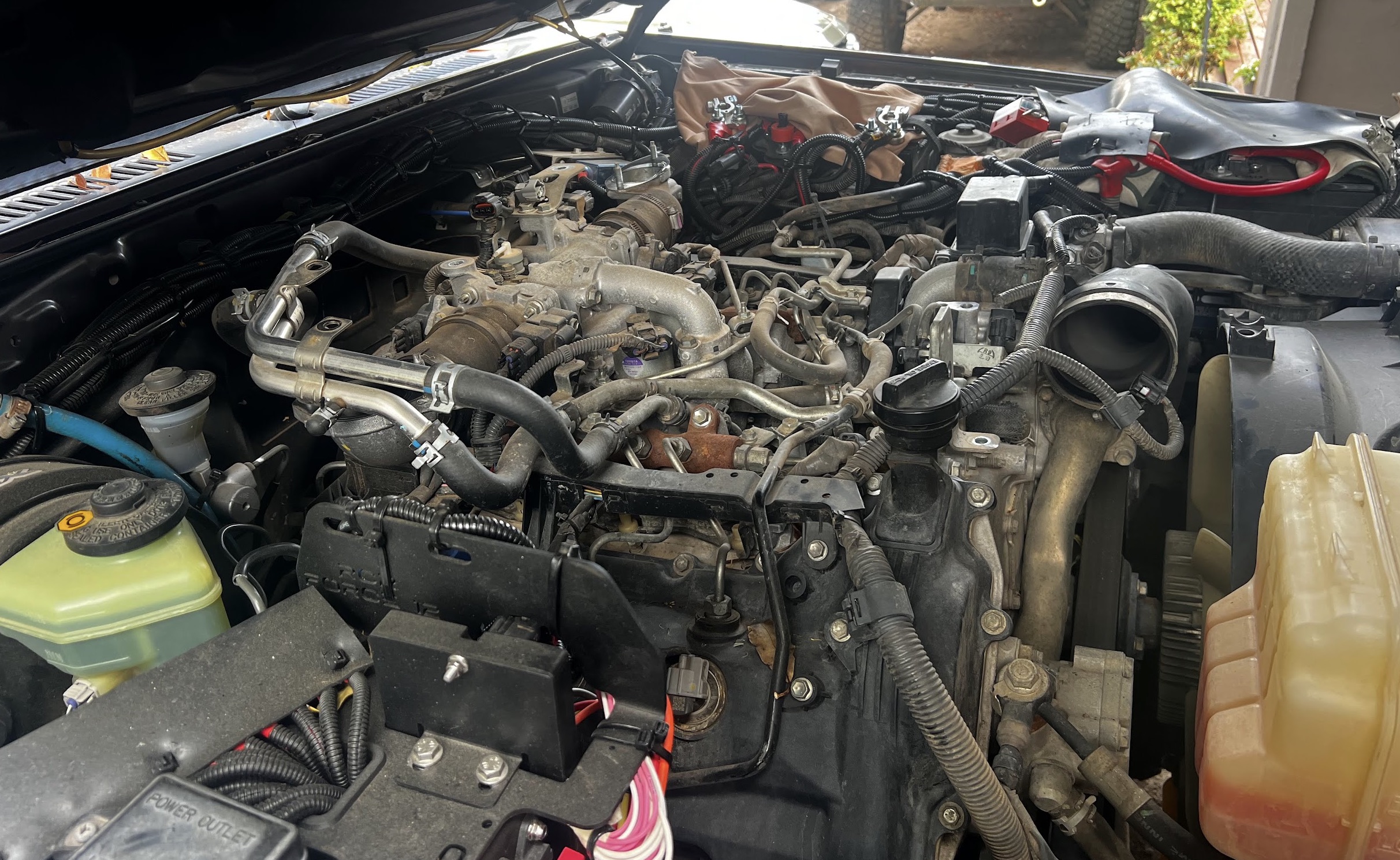
Day 1 - Getting the basic stuff into the engine bay
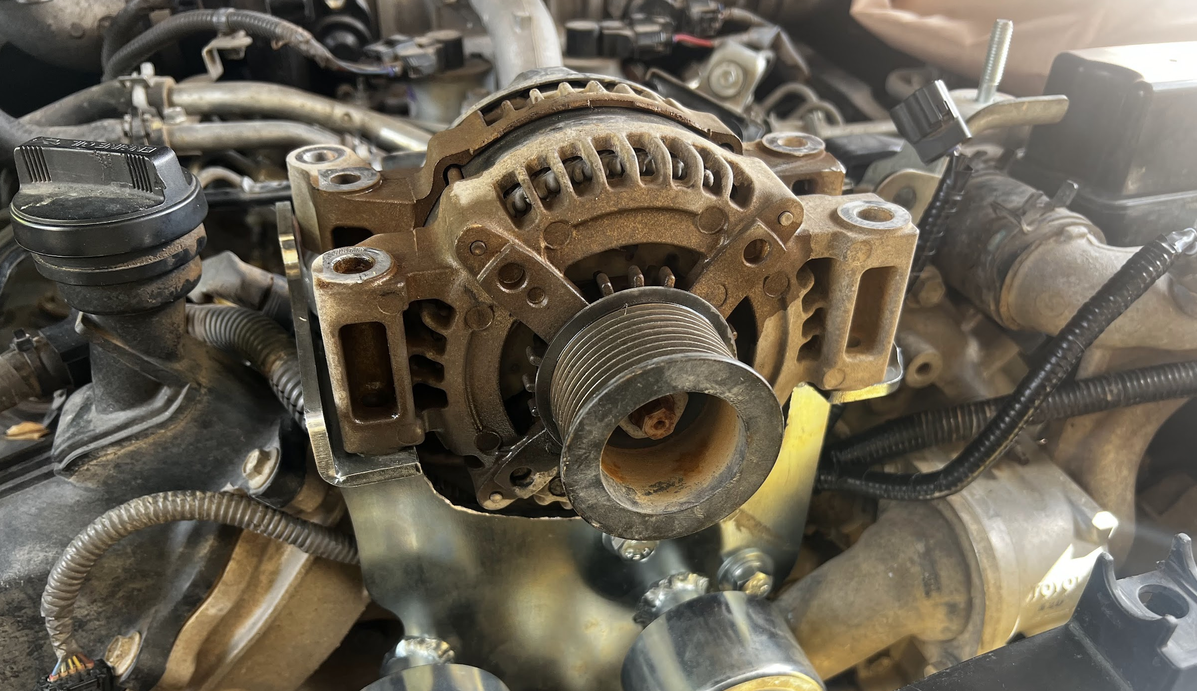
Summary of the day: We managed to figure out that the new Jaylec 240a alternator would not fit in the alternator bracket on top of the engine. No amount of bracket modification would enable us to mount the alternator as it bumbed into the timing case as well as the positive on the alternator was rubbing up against the engine block… almost a certainty of disaster. So a whole day to find out that the basic assumption of drop in componentry was wrong.
Here’s a picture of the top engine intercooler removed to allow us to access the area where the bracket and dual alternator was going to be installed.
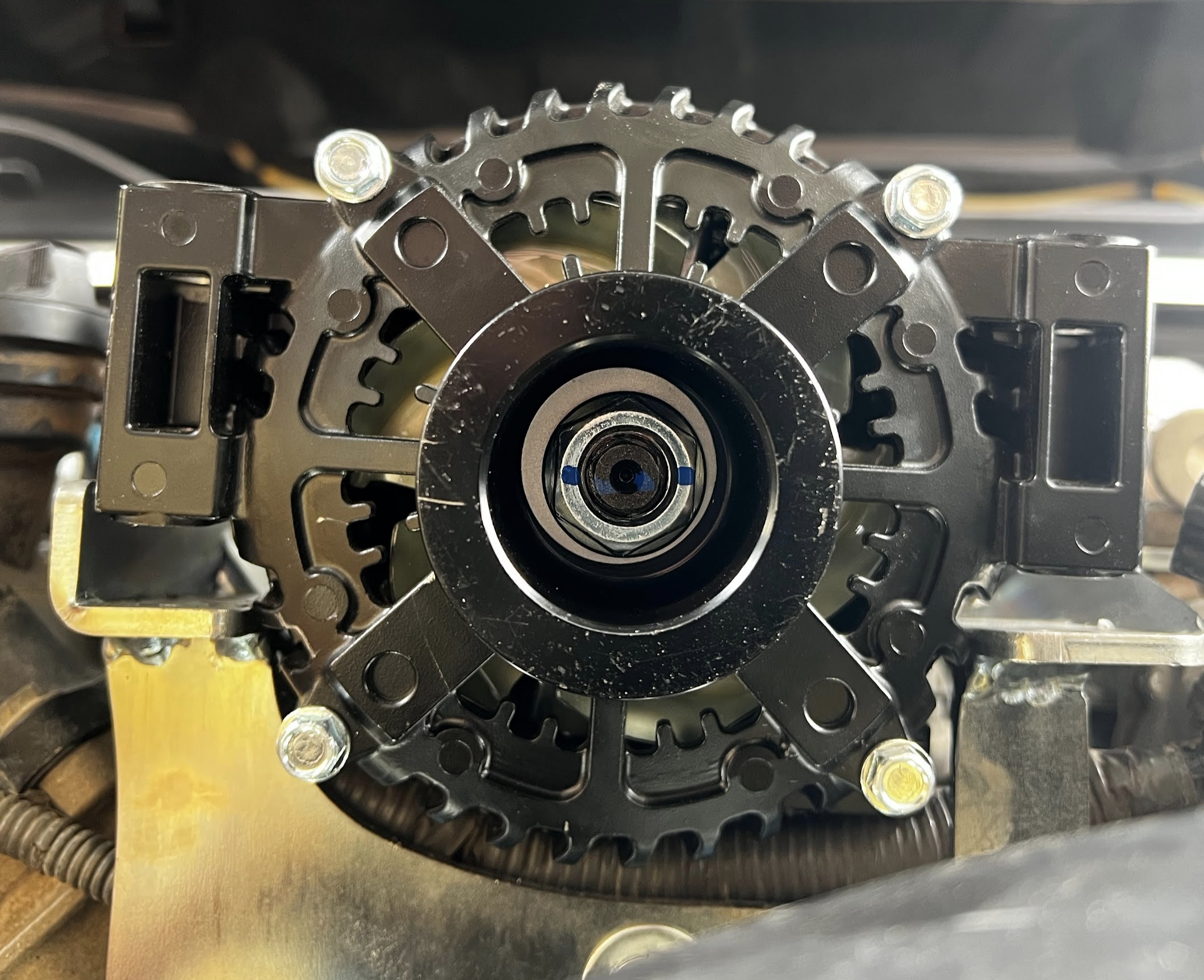
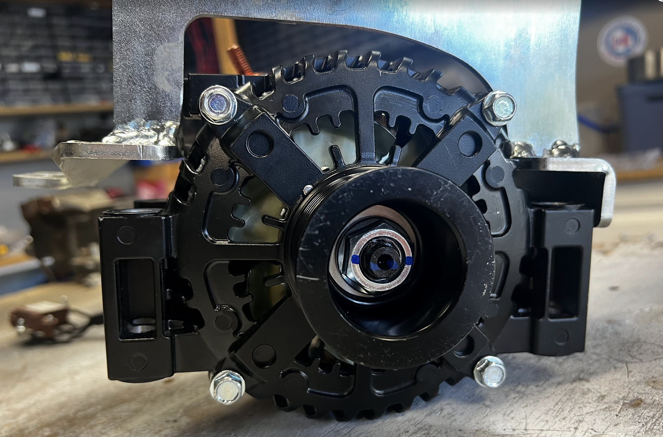
Here is the dual alternator bracket installed when it was un-modified. Looks neat!
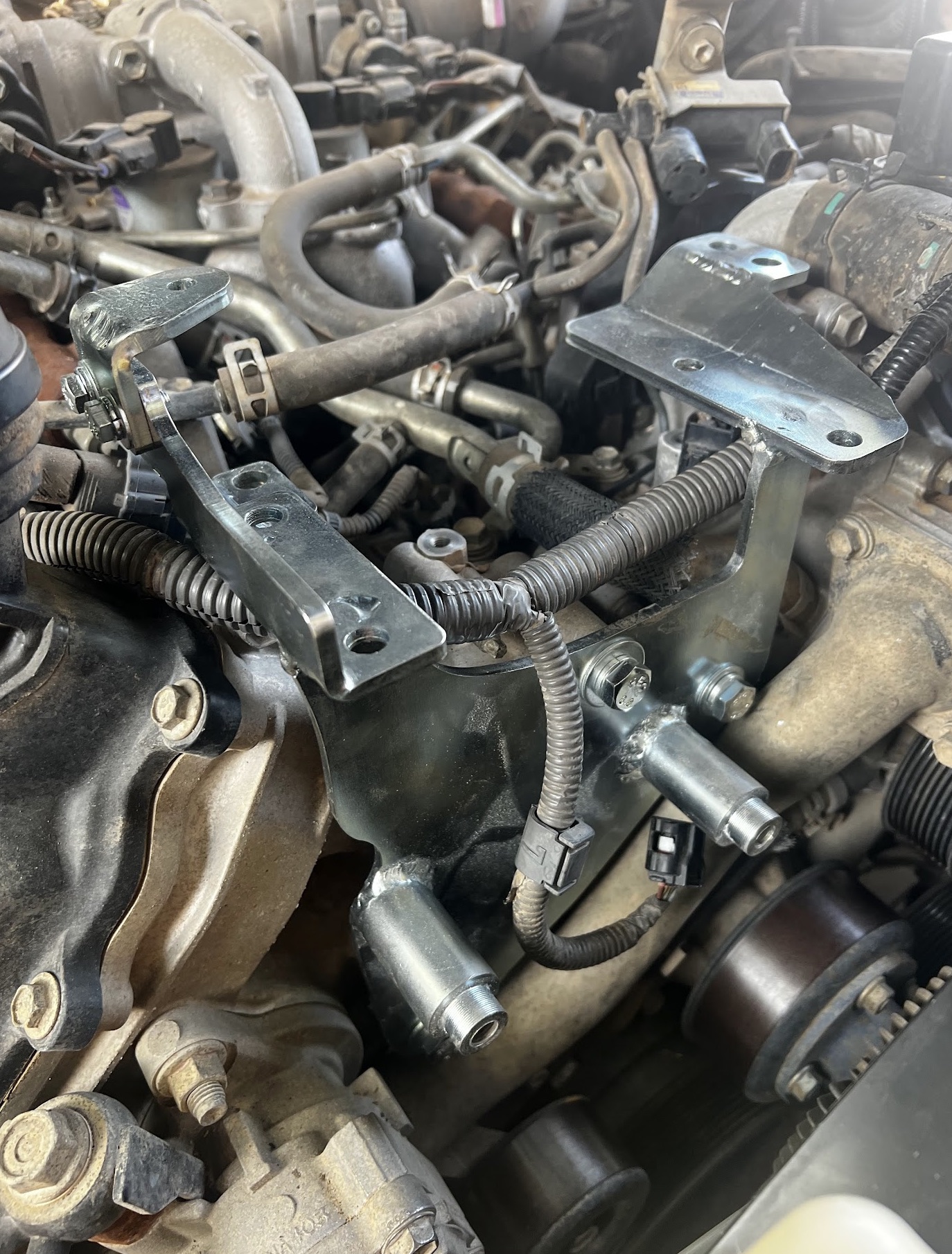
Another shot of the dual alternator bracket installed. Looks so nice and shiny…
It is a tight fit. That rubber hose clamped towards the right topside of the bracket is the one that needs to be pushed to the right with mounting another bracket.
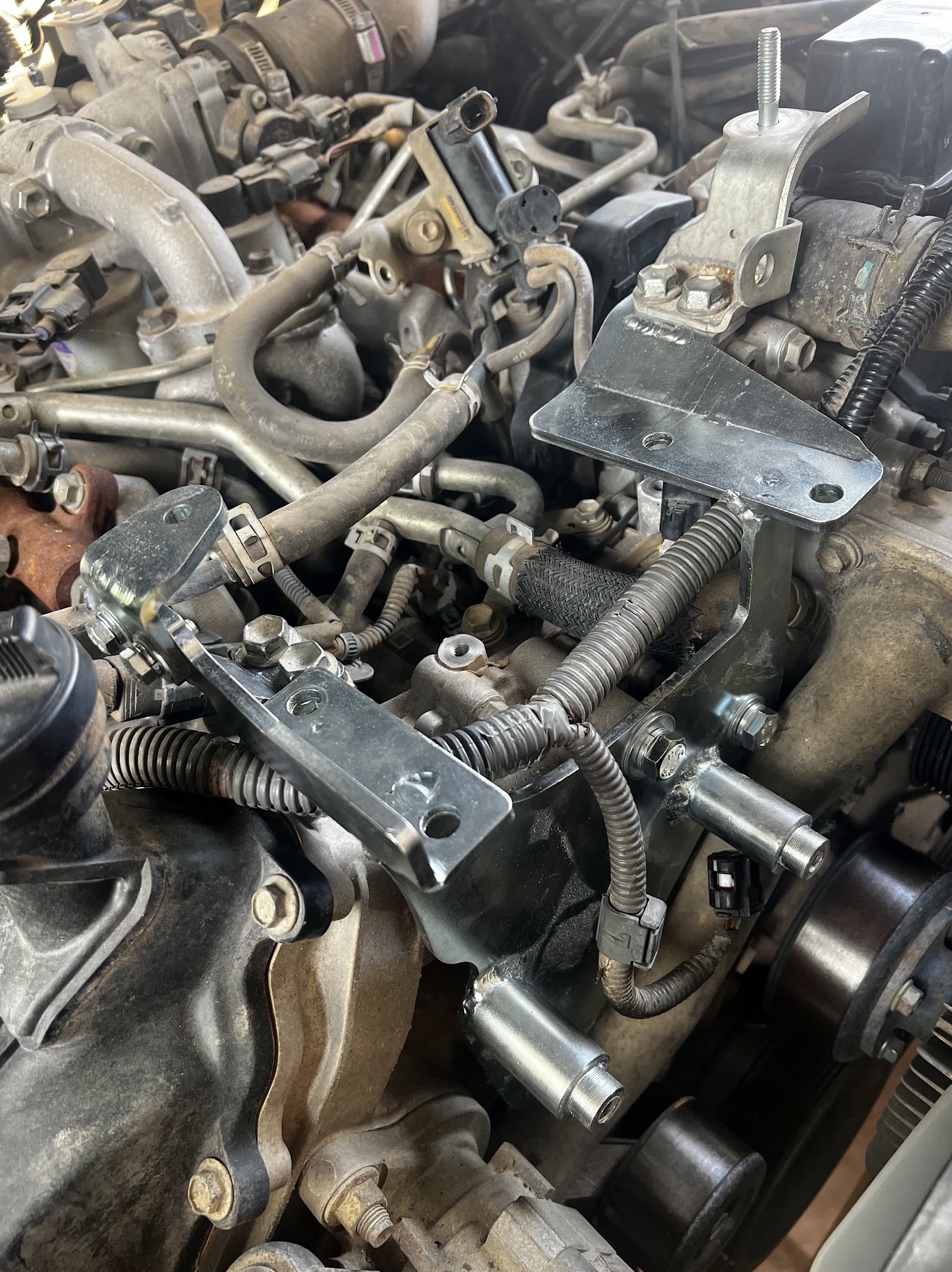
Yep. This part is fun and in the end, the modification to this specific alternator was not required. We still at this point believed that we could fit this 240a alternator to the top of the engine so the alternator connector needed to be relocated as there is no room underneath the alternator where it faces the engine block. In the end, we had to re-modify this back to stock when this particular alternator was moved down to the bottom stock alternator spot.
The points called out here are the screws and points that has to be relocated. The documentation from Rapid Air Inflation Systems was decent. Follow that.
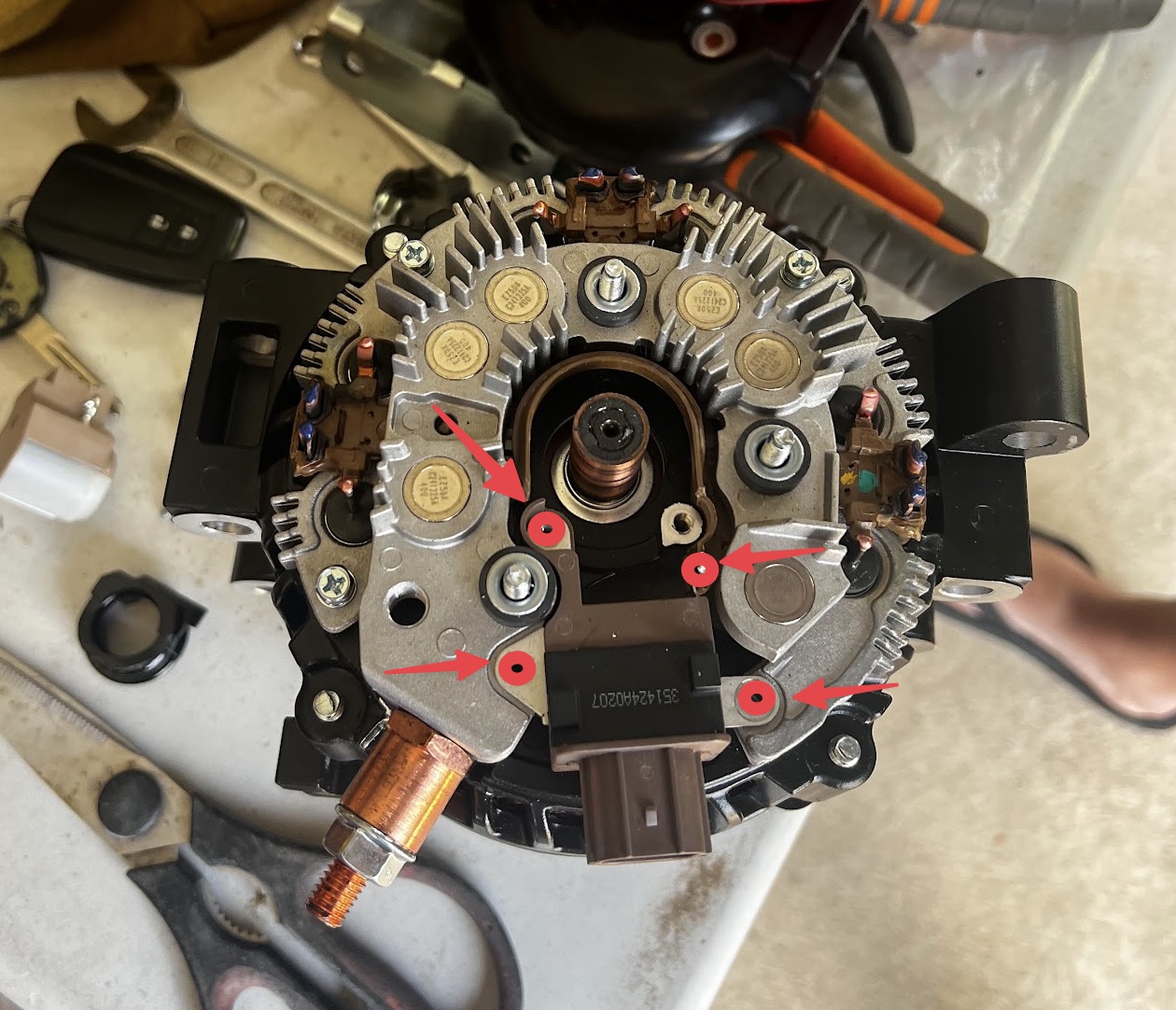
How it will need to look when modified.
Another picture of it modified.
Well.. we still believed that it would fit… it will not! Start with swapping the alternators and get the stock up in this position!
Day 2 - Realisation that it will not work and we have to swap the alternators around
Summary of the day: We found out that we had to swap the alternators. So day 2 was really to modify the top bracket to still try to fit the new 240a alternator, but in the end when we managed to squeeze the new alternator into the bracket… when we mounted it to the engine bay and tried to fit it… it hit the timing case so that was the end of that and we took the step to swap the alternators around making the stock on top and the new 240a at the bottom.
Oh! The new alternator will not fit in the bracket. Should have checked even that when we started. So much for drop in installation.
Yep. 100% confirmed. Will not work!
Yep. 100% confirmed. Will not work!
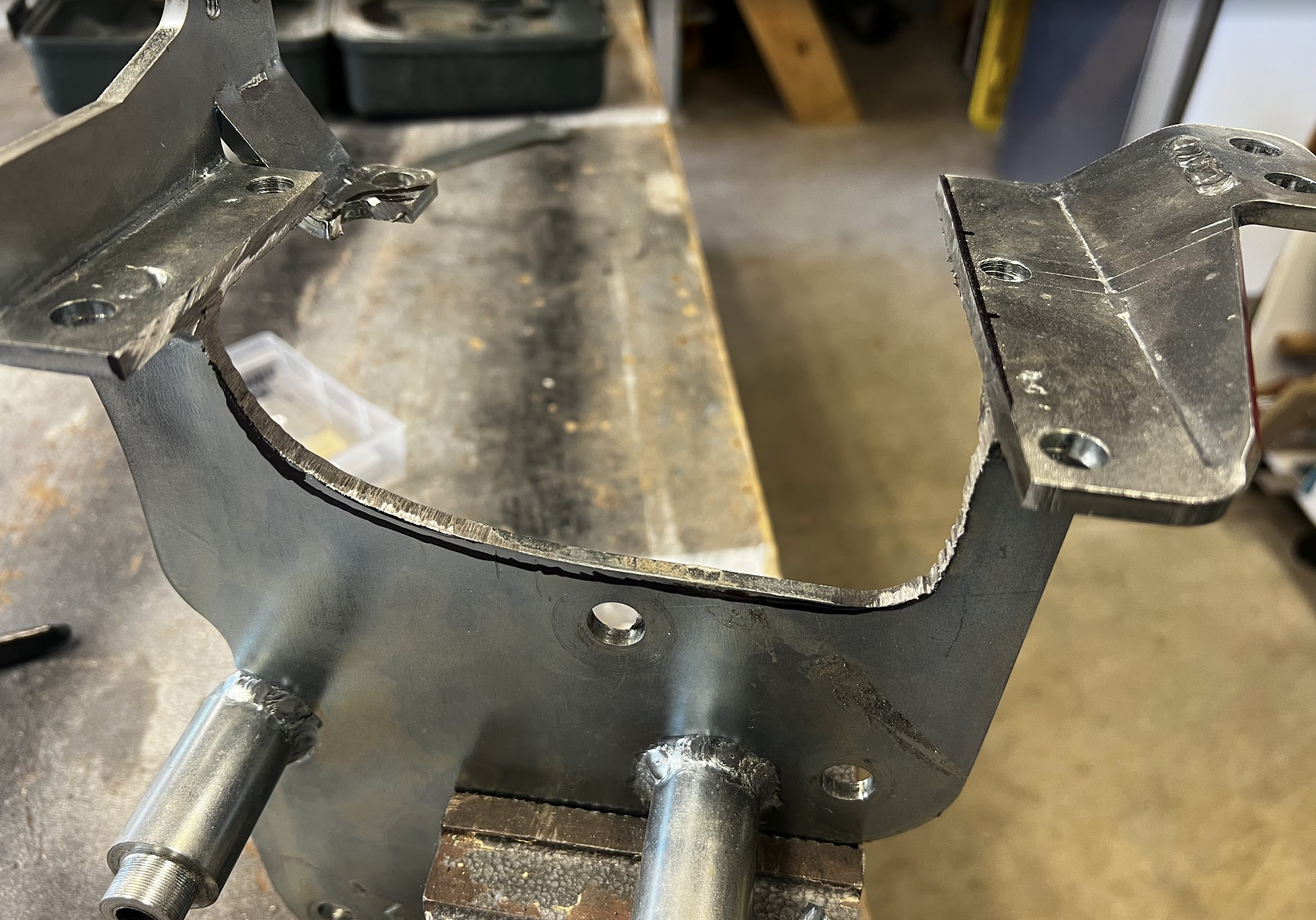
Out comes the angle grinder and we make an attempt to fit it.. but even doing this.. the alternator goes against the timing case…
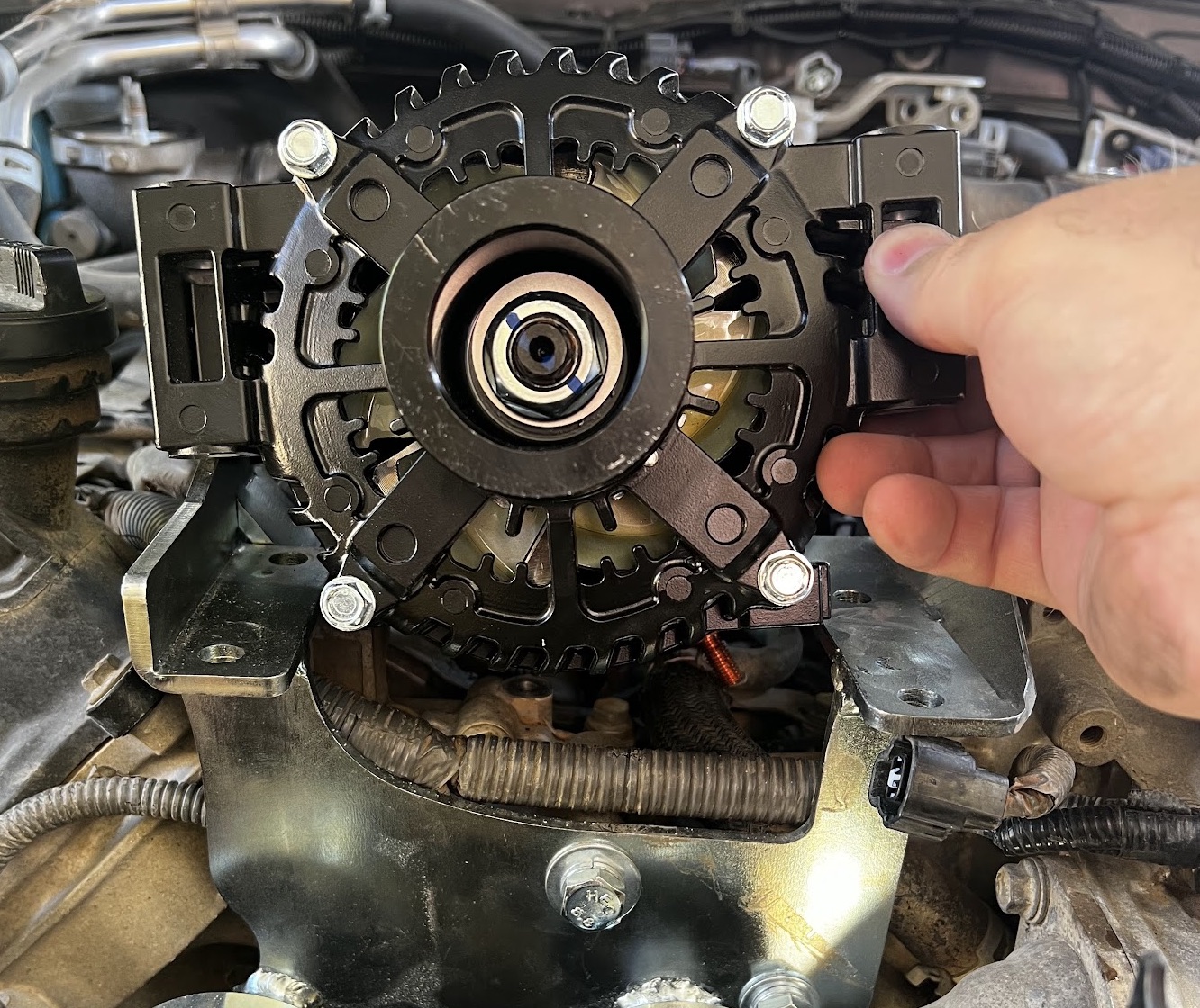
Ok. So we swap them around… now things start feeling slightly better…
Day 3 - Getting things in their right location and starting to assemble things again BUT BIGG PROBLEM WITTH THE BELT!
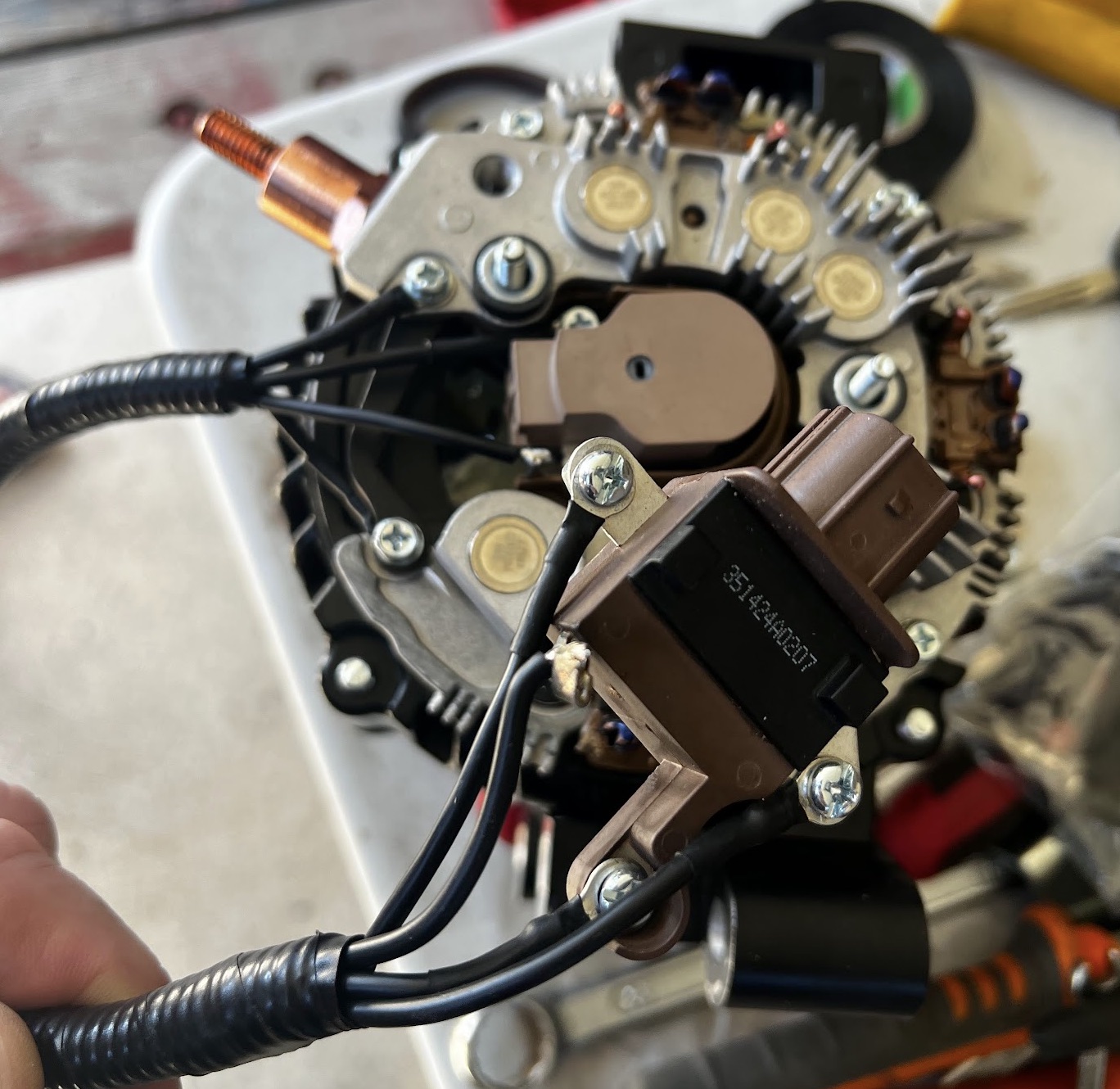
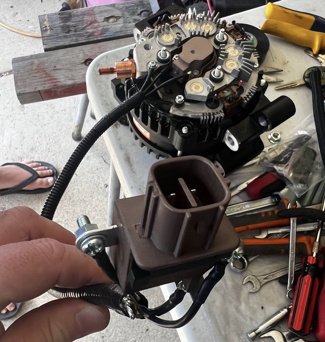
Summary of the day: Finally starting to put things together. We managed to get both alternator seated and starting to connect up the wiring. We decided to route the factory wiring up to the stock alternator on top so the cabling needed to be extended to fit. Then we prepared a 95mm2 welding cable from the new alternator up to a drivers side fuselink to terminate it there. We will run that to the main battery later.. but now also need to solder in the new Denso alternator socket to ‘Sense’ (IGN) and ‘Live’ (continous 12v). Did not get to finish it all but we are on a roll to get things mounted back together….. so it seems! BUUUT! Big problem, mounting this back together… now the belt was rubbing against the power steering pump!
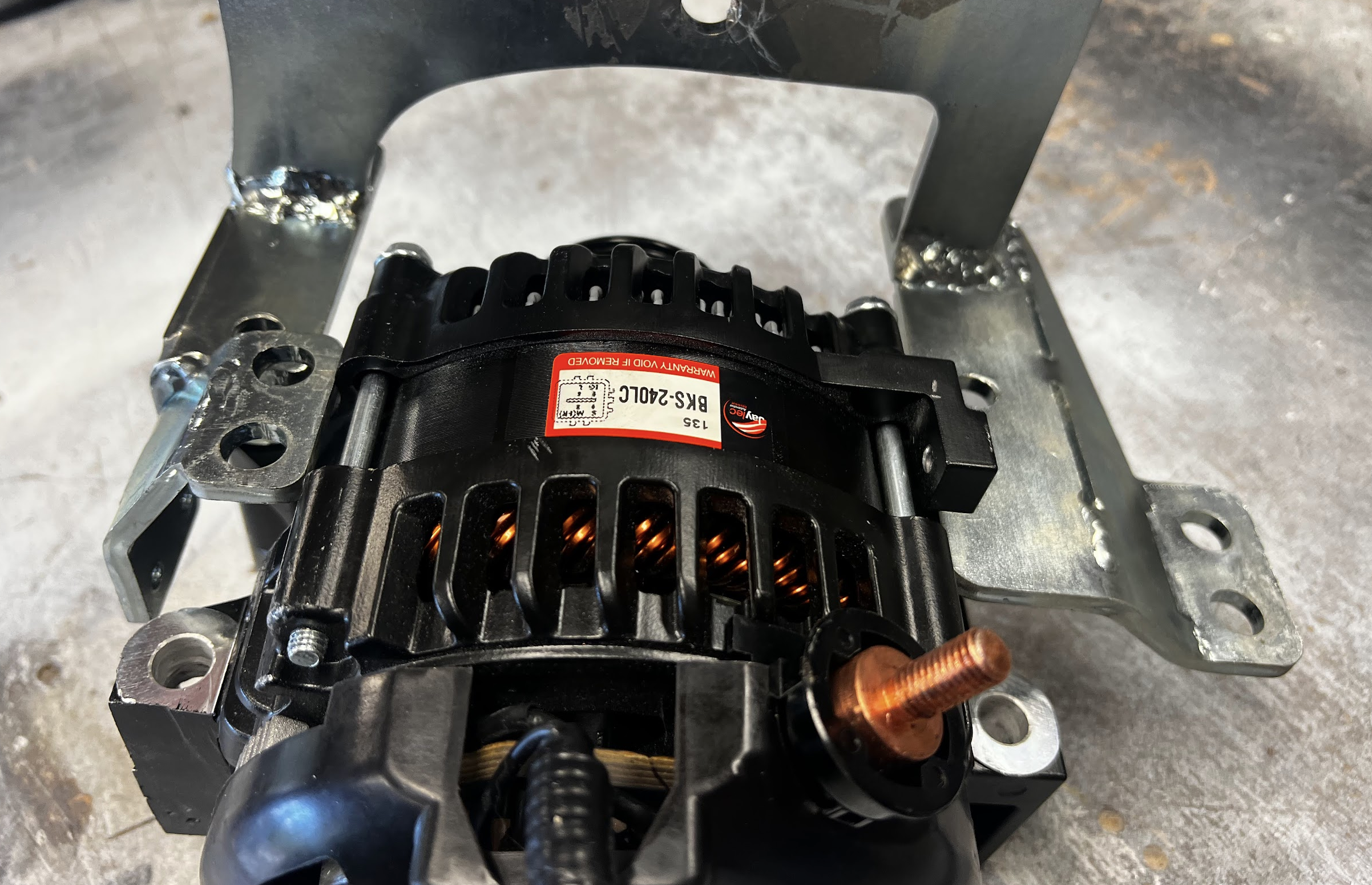
First off. We found an issue with the new alternator. We could not make it fit and we found that the factory holes in the alternator were cast in the wrong spot… so we had to bring out the drill with 13mm drill bit and make it bigger to fit the slot in bolts in the factory location. Crazy!
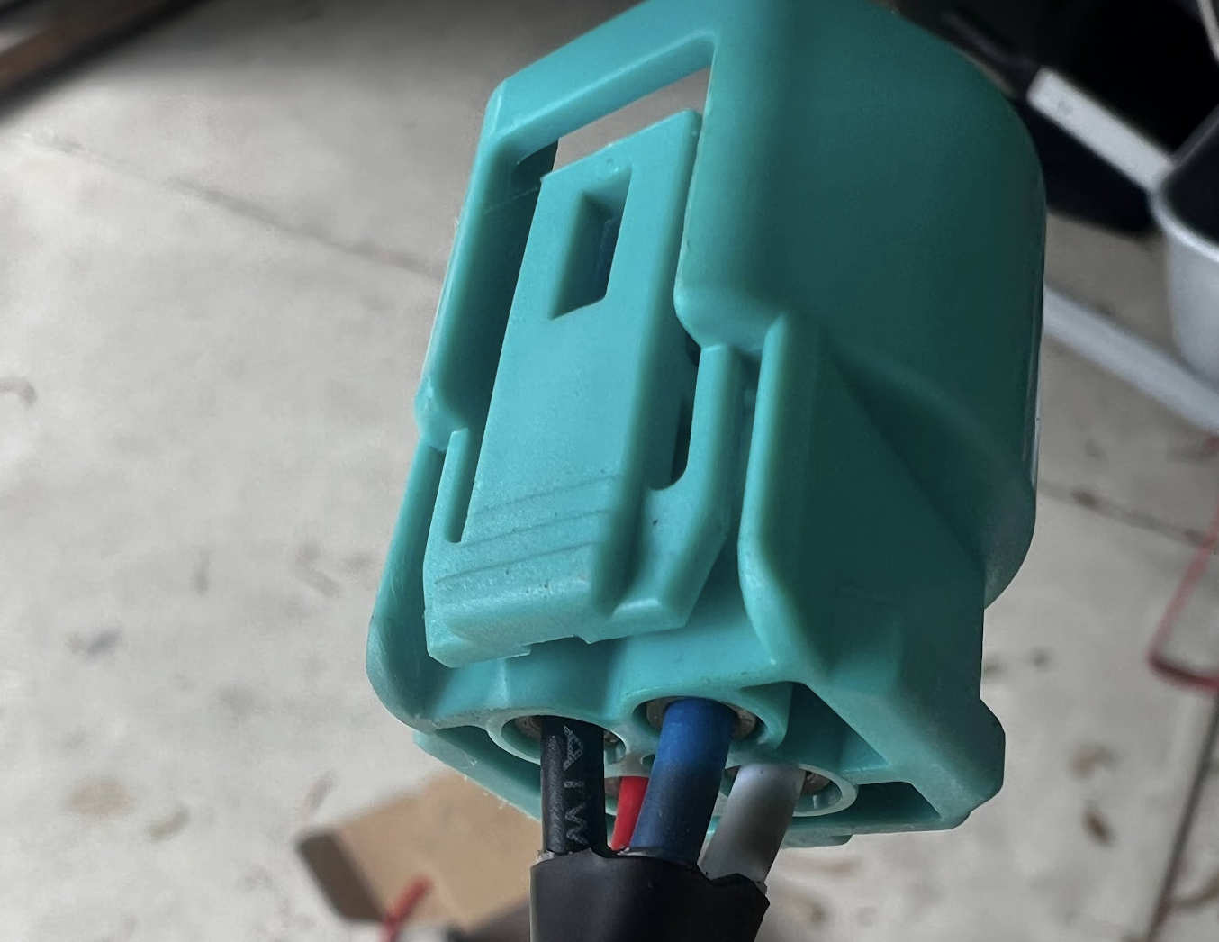
This is the item you need to buy and need to solder two of these wires into IGN and fixed 12v. More about that later.
But we ran into a big issue. The instructions from the manufacturer must have been for a different VDJ79 engine as the belt routed the same did not fit!! It ended up rubbing on the power steering pump!!!! Big problem!
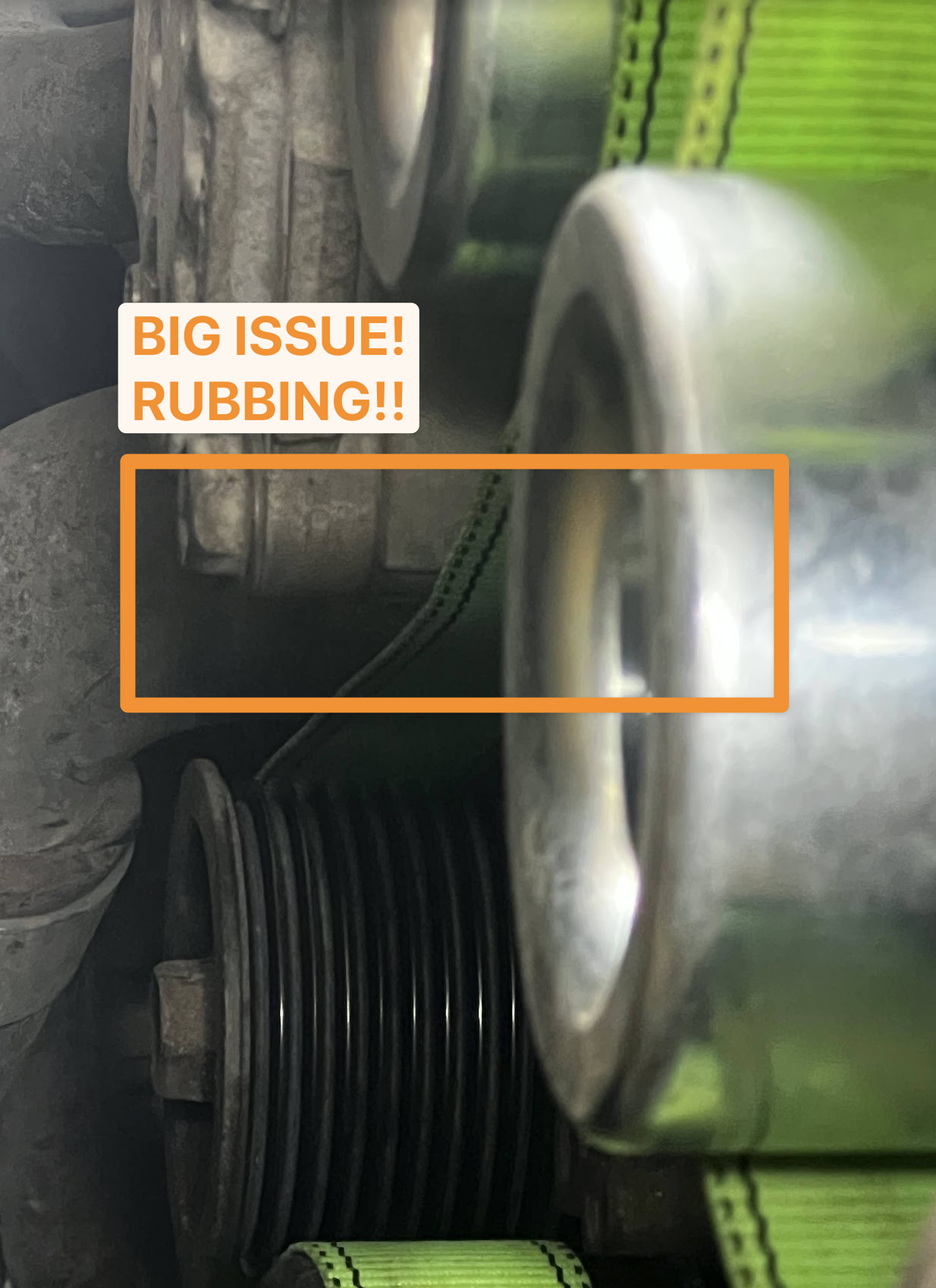
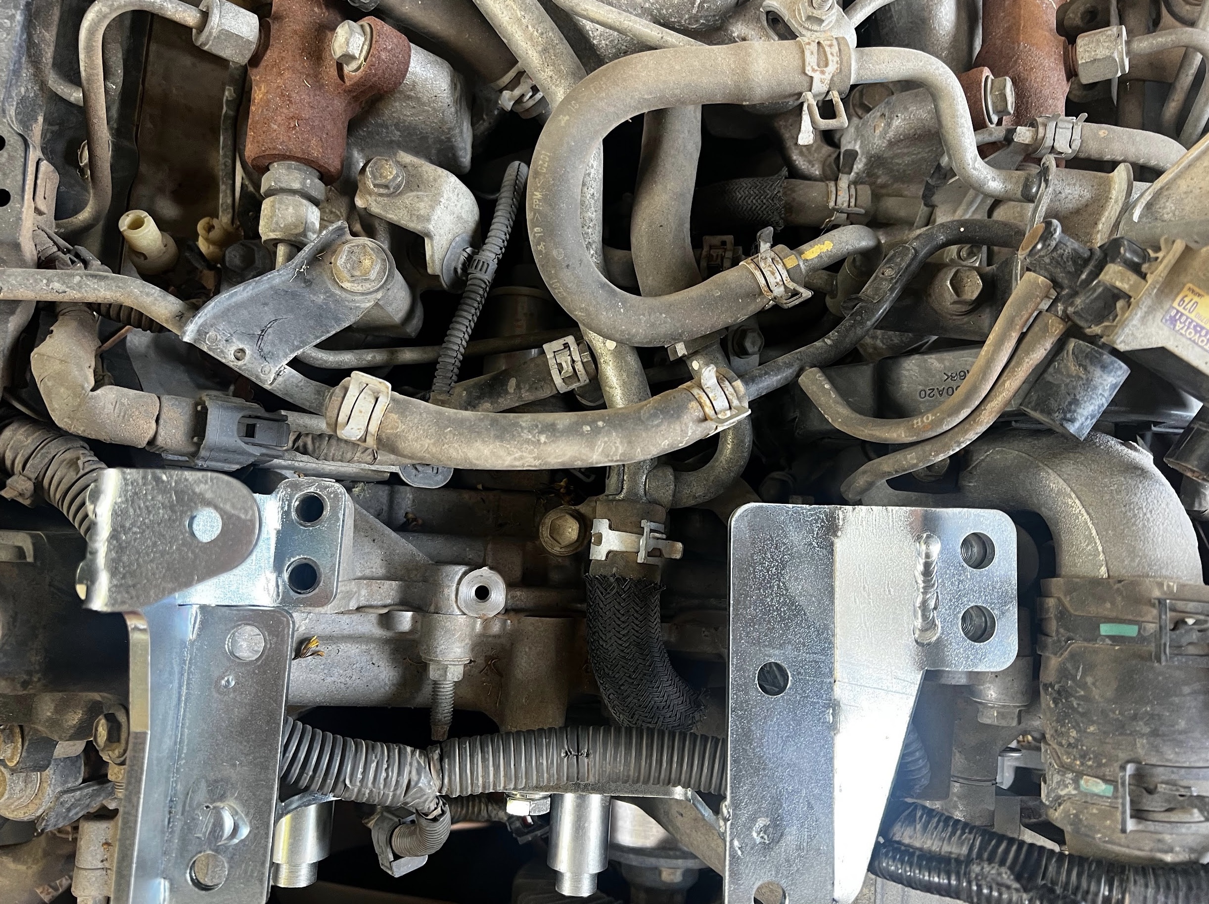
You can see more in this picture …
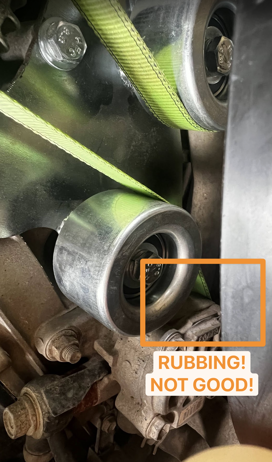
And in this picture you see the commentary of the problem that we now were facing.
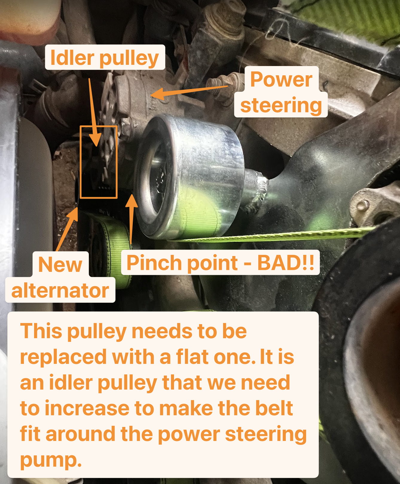
We are hoping the fix is simple and need to replace the one idler pulley with a flat one for the belt to rub up against. A slightly bigger flat pulley to make the belt fit past the power steering pump.
Day 4 - Trying (but failing) to putting it all back together
Summary of the day: Trying to get the car back on the road.. but today was not the day!
We have the offer of taking off the dual alternator bracket and shipping it over to Western Australia to get it rewelded when and if we find a belt that fits. However, we decided to get the car back on the road whilst we figure out a new 50mm OD flat pulley with 40mm width and a new 9PK2650 belt as the 9PK2580 that I sourced from Europe did not fit. Just a tad too short so that has to be returned.
We fit the original factory belt for now with the new 240a alternator down below. Still have to make the wired connections to the house battery etc. on that one, but that should be almost ready to go.
Besides that … the focus of the day was to sort out the air intake part but that was not as easy as the instructions made it out to be. We had to cut the intake pipe into the engine like this:
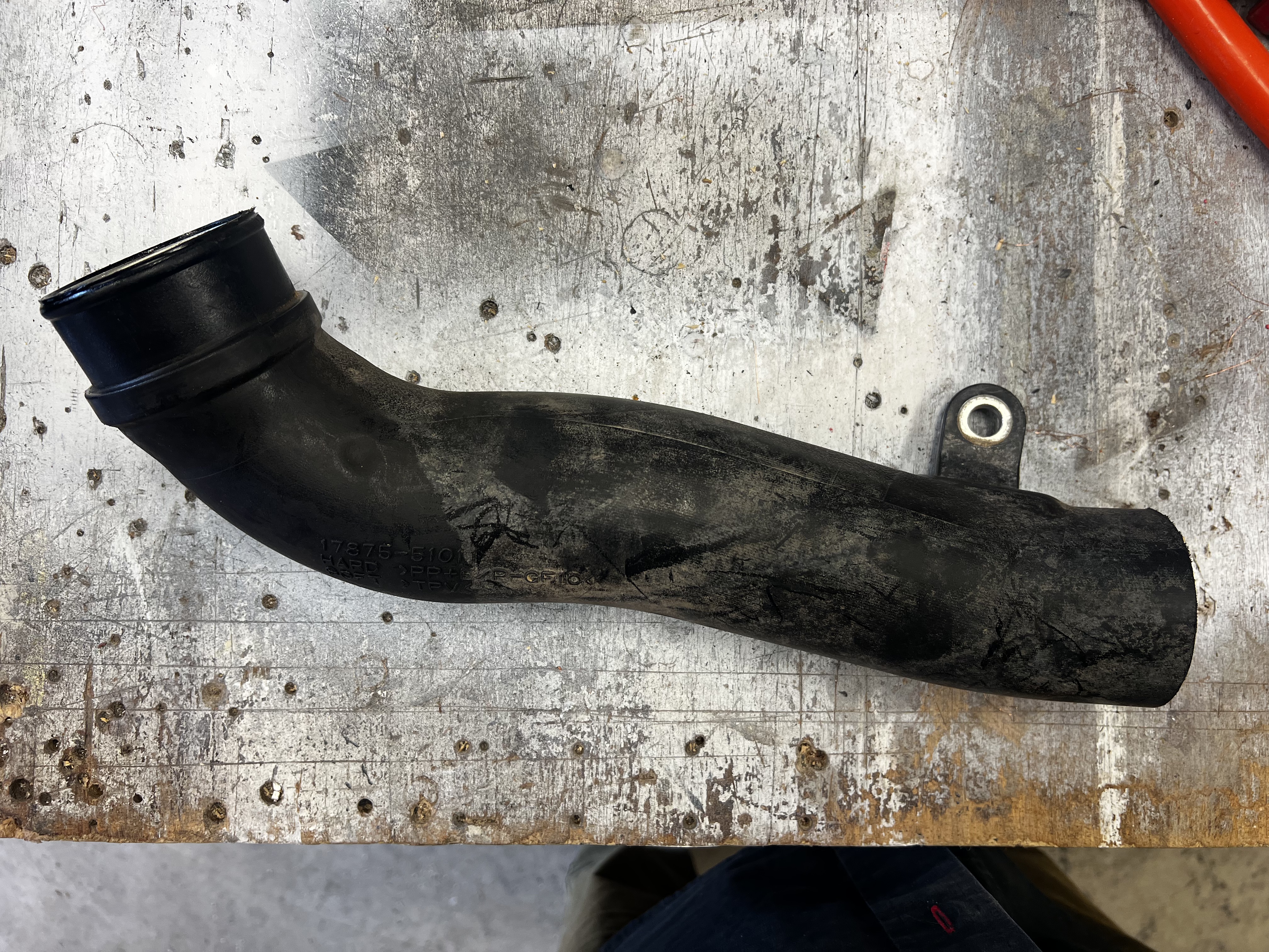
In the end, we had to work out a rough length to cut the pipe to in order to fit it with the items that were supplied to fit into the airbox. Not an easy part either but we are almost there we think. Just needed to get Repco to order in clamps to fit this all together. That is coming on Monday it seems, so at least we can get the air intake part sorted.
So now the issue is to find a replacement flat pulley for one of the stock idler pulleys in the engine. The stock is roughly 50mm outer diameter and 40mm wide to fit a 9PK belt. However, there are literally no such flat pulleys available so Google, ChatGPT, Gemini and much others were put to use to find something. In the end, there are supercharger kits and parts in the USA that does them but they are custom made, so not cheap. I ended up buying a DMS 50mm Supercharger Idler Pulley from DMS in the USA. There are a few other suppliers over there. Issue is that it will take some time to get here as I need to use a freight forwarding service to get it here. I am using ShipItTo if that’s of any use to you. Anyways, that flat pulley should have an inner bolt size that fit the stock idler pulley, so that’s a win. If that works, will just need to get two more as spares for the car given they are so hard to source.
Next issue was to locate the right size 9PK belt. We are not 100% sure what we need but we have measured it with a string… so think a 9PK2650 would work, or possibly (if we are lucky) a 9PK2642. Both are hard to get but trying to source in Australia, USA and Japan. There may be a supply out of the UK as well.
Either way, we are making progress, but slow… so will need a few more days to get this done. Though the intent of today was really to start to get the car back on the road as we have a “big” trip planned coming up on April 1st so really need the car back on the road.
Wiring considerations
Given the intent of this installation is to move the Safiery Victron based setup from my old LC79 to this LC79, we have to think about the wiring that we have to do. The following picture outlines the way I am currently thinking of wiring up the primary connections of the alternators in the engine bay and how that will be connected into the canopy where the Safiery Scotty 3kw dc/dc unit sits which charges the 48V system that powers the Victron Multiplus-II 5kw inverter etc.
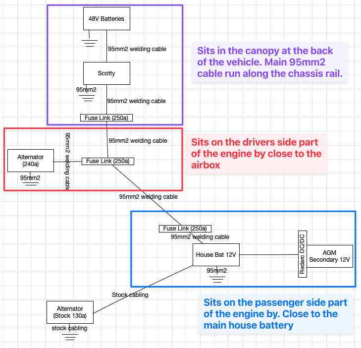
The primary thing here is to ensure that both active 12v connections and earths are connected properly. So what you see in the picture above is primary cabling is done via 95mm2 welding cable through 250a fuselinks. The welding cable is able to hold 540a but the way I am using it is to make sure that there is no voltage drops over the lengths of cable runs that I need to run.
There are a few things that I had as questions in context of this setup… they were all answered by Tom from Safiery which I am including here as reference:
Dual Alternators into Front AGM (130A + 240A)
In simple terms: the alternators do not “force” 270A into the AGM. Alternators are voltage-regulated devices. They supply current based on system demand and battery acceptance — not nameplate output. If:
The AGM is full
The 48V bank is full
Scotty is not requesting charge
Then system demand drops and the alternators back off to float-level output. They don’t continue pushing full current. Where current gets high is when:
The 48V bank is low
Scotty ramps up to supply 48V charge
There are active 12V loads
In that case Scotty can pull significant current from the 12V side. That’s when cabling and alternator health matter. The AGM won’t absorb 270A just because it’s available — battery internal resistance and regulator voltage prevent that. If everything is fully charged, alternator output falls back to maintenance level.
LS Trigger & 48V Supporting 12V
The Scotty unit will monitor via 12V LS voltage. When configured appropriately:
If 12V drops below threshold, Scotty can convert 48V → 12V
If 48V needs charge, Scotty pulls 12V → 48V
So yes — the 48V bank effectively becomes a stabilised reserve for the 12V system when required. It’s not a permanent parallel system, but under low-voltage conditions the 48V side can support the front batteries and secondary circuits. That’s one of Scotty’s strengths — it stabilises both sides of the architecture rather than just acting as a one-way DC charger.
Scotty’s Alternator Temp Sensor
I asked whether the old sensor could be cut from the old harness and re-soldered and connected on the new car. The answer was that you can relocate the sensor based on these requirements:
Use automotive-grade twin-core cable
Maintain similar gauge to original (typically ~18–20AWG equivalent)
Keep joins soldered or properly crimped and sealed
Placement: With dual alternators, install the temp sensor on the alternator That is connected to Scotty, It will be doing the most work. Make sure to mount it to the frame of the alternator and not the positive terminal. We are measuring how hot the alternator is getting under load. That gives you real protection where thermal load is highest.
Safiery’s comments on the cabling concept that I have
Based on your description: Both alternators → main front AGM → 95mm² fused → Scotty. Electrically, that’s fine. Whether the alternator lands on a busbar or directly on the battery positive is functionally the same — as long as:
All terminations are mechanically solid
Fusing is correctly positioned
Cable lengths are minimised
Voltage drop is controlled
Nothing you’ve described raises a red flag from a topology standpoint. The key variables remain:
Alternator duty cycle
Thermal management
Cable integrity
Proper fuse coordination
Overall, my understanding in developing the new cabling for the new car is on track.
Day 5 - Putting the air intake parts and hooking in the new alternator (only) to get the car back on the road
Summary of the day: ….
Intent of this day will be to get the car back on the road. Still wont be working with two alternators but it will be back on the road.
Conclusion and next steps
Then we’re not even finished. This is just the engine bay prep that is required and I now can start running the cabling to the 48v system in the canopy. That on its own is also a big job..